Signal Integrity in Rigid Flex PCB Designs
Rigid-flex PCBs integrate rigid and flexible elements into a single unit to reduce component count, streamline assembly, increase reliability, and reduce costs. However, the seamless amalgamation of rigid and flexible components also poses several design challenges. One major issue is signal integrity. To ensure that your rigid flex pcb design delivers optimal performance, you must take into account the unique properties of the material used to create the flexible portion of the board, impedance control, and thermal management.
Using the right materials for the rigid and flexible sections of the PCB helps to mitigate thermal expansion and contraction issues, which can cause short circuits, open circuits, and other electrical failures. Additionally, choosing the proper materials will minimize EMI and other electromagnetic interference (EMI) problems.
Mechanical durability is another important consideration for rigid flex pcb designs. Adhering to strict bend radius guidelines and designing for stress distribution can help prevent mechanical failure of conductive traces, such as shorts or open circuits. The use of Zero Insertion Force (ZIF) connectors in areas that require transitions between rigid and flexible sections can help to further mitigate potential stress-induced failures.
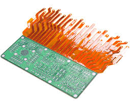
How to Optimize Signal Integrity in Rigid Flex PCB Designs
The integration of rigid and flexible elements in rigid-flex PCBs can significantly reduce assembly time. However, it can also complicate the electrical connections. The overlapping of rigid and flexible regions can introduce signal degradation and interference due to different electrical characteristics, such as varying thermal expansion, mechanical fatigue resistance, and conductor thickness. To minimize these effects, designers must carefully plan the placement of vias to ensure that signals can traverse the entire circuit with minimal distortion.
High-speed circuits on rigid flex boards can generate significant amounts of heat, which can negatively impact the performance of the device. To prevent excessive heat buildup, you must use appropriate thermal management methods, such as adding heat sinks and incorporating thermal vias to enhance heat dissipation. Similarly, you should implement sound shielding and grounding techniques to mitigate electromagnetic interference (EMI) and other potential electronic failures.
Impedance control is an important factor for rigid-flex designs because the flexible portions of the PCB have a different characteristic impedance than their rigid counterparts. This difference can result in loss of signal transmission and distortions, which can significantly degrade the quality of the end product. To prevent this from occurring, you must accurately calculate and control impedance using an impedance calculator or simulation tool.
The type of copper and core thickness you choose for your flex circuits can also impact signal integrity. For example, microstrip traces allow for thinner, controlled impedance compared to stripline PCBs, which require thicker copper and cores. To achieve the highest level of signal integrity, it is recommended to choose a differential pair for digital and analog signal paths.
Proper grounding is crucial for ensuring the stability of your RF circuits and digital signals. To avoid RF crosstalk, you should consider implementing a shielded ground plane and using differential pairs in digital and analog signal paths.